Manual.ly Logo

ABB SV/S 30.640.5.1 Instrukcja-Obslugi

0,0 · 0 Oceny

Instrukcja PDF · 2 Strony

Polski

M: OA-GPT-5-NAN
strona

/ 2

Loading...
4b6accbffe793a964f572a7beec3c68833c0 page 1
Montage- und Betriebsanleitung
Installation and Operating Instructions
Mode d´emploi
Instrucciones de montaje de servicio
Istruzioni per l´uso
Montage- en bedieningshandleiding
Instrukcja montażu i eksploatacji
Руководство по монтажу и эксплуатации
安装和操作手册
SV/S 30.640.5.1, SV/S 30.320.2.1
Spannungsversorgung mit Diagnosefunktion
Power Supply with diagnostics
Alimentation électrique avec diagnostics
Fuente de Alimentación con diagnóstico
Alimentatore di linea con diagnostica
Voeding met diagnose functies
PL
Zasilacz KNX z diagnostyką
RU
Блок питания с диагностикой
CN
电源供应器带总线监测
ABB i-bus
®
KNX
2CDG941089P0004
DE
EN
FR
IT
NL
ES
DE EN FR ES
Busanschlussklemme
Programmiertaste und -LED (rot)
Schilderträger
Taste Reset und LED (rot)
LED Comm. Error (gelb)
LED Telegr. (gelb)
Anschluss Versorgungsspannung U
s
LED U
N
OK (grün)
i
LED I > Imax (rot)
j
LED Busstrom (7 x gelb)
k
Hilfsspannungsausgang
(nur bei SV/S 30.640.5.1)
Gerätebeschreibung
Die KNX-Spannungsversorgungen mit integrierter Dros-
sel erzeugen und überwachen die KNX-Systemspan-
nung. Für Diagnosezwecke können Busstrom, Bus-
spannung und weitere Meldungen über KNX gesendet
werden. Der Spannungsausgang ist kurzschluss- und
überlastsicher. Die LEDs zeigen die Busstromaufnahme
und den Status der Linie bzw. des Gerätes an. Das
Gerät vom Typ SV/S 30.640.5.1 verfügt über einen
zusätzlichen 30 V DC-Hilfsspannungsausgang. Dieser
kann zur Speisung einer weiteren Buslinie (in Verbin-
dung mit einer separaten Drossel) verwendet werden.
Technische Daten (Auszug)
Versorgung
Versorgungsspannung U
s
100 – 240 V AC; 50/60 Hz
85…265 V AC
Impuls Spannung 4.000 V (nach UL 60730-1)
Verlustleistung (bei Nennbetrieb)
- SV/S 30.320.2.1 2,5 W
- SV/S 30.640.5.1 4 W
Leistungsaufnahme (bei Nennbetrieb)
- SV/S 30.320.2.1 12,5 W
- SV/S 30.640.5.1 24 W
Ausgänge
KNX 1 Linie (verdrosselt)
Nennspannung U
N
30 V DC +1/-2 V, SELV
Nennstrom I
N
- SV/S 30.320.2.1 320 mA
- SV/S 30.640.5.1 640 mA
Dauerkurzschlussstrom
- SV/S 30.320.2.1 < 0,8 A
- SV/S 30.640.5.1 < 1,4 A
Netzausfallüber-
brückungszeit
200 ms
Hilfsspannungsausgang (nur SV/S 30.640.5.1)
Nennspannung U
N
30 V DC +1/-1 V, SELV
Anschlüsse
Versorgungsspannung Schraubklemme
0,2…2,5 mm² feindrähtig
0,2…4 mm
2
eindrähtig
KNX Busanschlussklemme
Temperaturbereich
Betrieb - 5 °C... + 45°C
Abmessungen und Gewicht
H x B x T 90 x 72 x 64,5 mm
Breite in TE 4 Module à 18 mm
Gewicht Etwa 0,26 kg
Approbationen
EIB / KNX nach EN 50 090-1, -2
CE-Zeichen gemäß EMV-Richtlinien
Getestet nach UL
60730-1 / CSA E60730
Typ 1.C Aktion nach
UL 60730-1
Gehäuse
Schutzart IP20 nach EN 60 529
Schutzklasse II nach DIN EN 61 140
Überspannungskategorie III nach EN 60 664-1
Verschmutzungsgrad 2 nach EN 60 664-1
Luftdruck Atmosphäre bis 2.000 m
Einbaulage Beliebig
Bedienung und Anzeige
Programmiertaste
und -LED (rot)
zur Vergabe der physikali
-
schen Adresse
LED U
N
OK (grün) AN: Busspannung OK
LED I > Imax (rot) AN: Überlast
LEDs Busstrom (7 x gelb) AN: aktueller Busstrom
LED Telegr. (gelb) AN: Telegrammverkehr
LED Comm. Error (gelb) AN: Kommunikationsfehler
LED (rot) u. Taste Reset AN: Reset der Linie.
Zum Auslösen eines Reset die
Taste so lange betätigen bis
die LED an ist. Die Linie wird
für 20 Sekunden spannungs
-
frei geschaltet. Danach erlischt
die LED wieder.
Der Reset ist beendet.
Montage
Das Gerät ist geeignet zum Einbau in Verteilern oder
Kleingehäusen für Schnellbefestigung auf 35 mm Trag
-
schienen, nach DIN EN 60715. Die Zugänglichkeit des
Gerätes zum Betreiben, Prüfen, Besichtigen, Warten
und Reparieren muss gemäß DIN VDE 0100- 520
sichergestellt sein.
Anschluss
Der elektrische Anschluss erfolgt über Schraubklem-
men. Die Klemmenbezeichnungen be󰘰nden sich auf
dem Gehäuse. Die Verbindung zum KNX erfolgt über
die mitgelieferte Busanschlussklemme.
Inbetriebnahme
Die Inbetriebnahme erfolgt mit der Engineering Tool
Software (ETS). Eine ausführliche Beschreibung der
Parametrierung und Inbetriebnahme 󰘰nden Sie in der
technischen Dokumentation des Gerätes. Es ist darauf
zu achten dass die aktuellen Programme verwen
-
det werden. Diese 󰘰nden Sie zum Download unter
www. abb.com/knx.
Wichtige Hinweise
Warnung! Gefährliche Spannung! Installation nur
durch elektrotechnische Fachkraft. Bei der Planung
und Errichtung von elektrischen Anlagen sind die
einschlägigen Normen, Richtlinien, Vorschriften und
Bestimmungen zu beachten.
- Gerät bei Transport, Lagerung und im Betrieb vor
Feuchtigkeit, Schmutz und Beschädigung schützen!
- Gerät nur innerhalb der spezi󰘰zierten technischen
Daten betreiben!
- Gerät nur im geschlossenen Gehäuse (Verteiler)
betreiben!
Um gefährliche Berührungsspannung durch Rückspei
-
sung aus unterschiedlichen Außenleitern zu vermei-
den, muss bei einer Erweiterung oder Änderung des
elektrischen Anschlusses eine allpolige Abschaltung
vorgenommen werden
Reinigen
Verschmutzte Geräte können mit einem trockenen
Tuch gereinigt werden. Reicht dies nicht aus, kann ein
mit Seifenlösung leicht angefeuchtetes Tuch benutzt
werden. Auf keinen Fall dürfen ätzende Mittel oder
Lösungsmittel verwendet werden.
Wartung
Das Gerät ist wartungsfrei. Bei Schäden (z.B. durch
Transport, Lagerung) dürfen keine Reparaturen vor-
genommen werden.
SV/S 30.640.5.1
SV/S 30.320.2.1
Bus Connection Terminal
Programming button and LED (red)
Label carrier
Reset button and LED (red)
Comm. Error LED (yellow)
Telegr. LED (yellow)
Power supply connection U
s
U
N
OK LED (green)
i
I > Imax LED (red)
j
Bus current LED (7 x yellow)
k
Auxiliary voltage output
(only with SV/S 30.640.5.1)
Device description
The KNX power supply units with integrated choke
produce and monitor the KNX system voltage. The bus
current, bus voltage and other messages can be sent
via KNX for diagnostic purposes. The voltage output is
short-circuit and overload protected. The LEDs indicate
the bus current consumption and the status of the line
or device. The SV/S 30.640.5.1 device type features
an additional 30 V DC auxiliary voltage output. It can
be used to power an additional bus line (in combination
with a separate choke).
Technical data (excerpt)
Supply
Supply voltage U
s
100 – 240 V AC; 50/60 Hz
85…265 V AC
Impulse Voltage 4,000 V (acc. UL 60730-1)
Leakage loss (during normal operation)
- SV/S 30.320.2.1 2.5 W
- SV/S 30.640.5.1 4 W
Power consumption (during nominal operation)
- SV/S 30.320.2.1 12.5 W
- SV/S 30.640.5.1 24 W
Outputs
KNX 1 line (with choke)
Rated voltage U
N
30 V DC +1/-2 V, SELV
Rated current I
N
- SV/S 30.320.2.1 320 mA
- SV/S 30.640.5.1 640 mA
Continuous short-circuit current
- SV/S 30.320.2.1 < 0.8 A
- SV/S 30.640.5.1 < 1.4 A
Mains failure
bridging time
200 ms
Auxiliary voltage output (only SV/S 30.640.5.1)
Rated voltage U
N
30 V DC +1/-1 V, SELV
Connections
Supply voltage Screw terminal
0.2…2.5 mm² stranded
0.2…4 mm
2
solid
KNX Bus Connection Terminal
Temperature range
Operation - 5 °C... + 45°C
Dimensions and weight
H x W x D 90 x 72 x 64.5 mm
Width in space units 4 modules at 18 mm
Weight Approx. 0.26 kg
Approvals
EIB / KNX Compliant to EN 50 090-1, -2
CE mark In accordance with the EMC
guidelines
Tested according UL
60730-1 / CSA E60730
Type 1.C Action acc.
UL 60730-1
Housing
Enclosure IP20 to EN 60 529
Safety class II to DIN EN 61 140
Overvoltage category III according to EN 60 664-1
Pollution degree 2 according to EN 60 664-1
Atmospheric pressure Atmosphere up to 2,000 m
Mounting position As required
Operation and display
Programming button
and LED (red)
For assignment of the physi
-
cal address
U
N
OK LED (green) ON: Bus voltage OK
I > Imax LED (red) ON: Overload
Bus current LEDs (7 x
yellow)
ON: Momentary bus current
Telegr. LED (yellow) ON: Telegram tra󰘲c
Comm. Error LED (yellow)ON: Communication error
Reset button and LED (red)ON: Line reset.
To initiate a reset, press the
button until the LED comes
on. The line is disconnected
from the voltage supply for
20 seconds. The LED then
switches o󰘯 again.
Reset is ended.
Mounting
The device is suitable for installation in the connection
unit or small enclosures for fast installation on 35 mm
mounting rails to DIN EN 60715. Accessibility of the
device for the purpose of operation, testing, visual
inspection, maintenance and repair must be provided
compliant to DIN VDE 0100- 520.
Connection
The electrical connection is implemented using screw
terminals. The terminal designations are located on the
housing. The connection to the KNX is implemented
using the supplied Bus Connection Terminal.
Commissioning
Commissioning is performed with the Engineering Tool
Software (ETS). A detailed description of
parameterization and commissioning can be found
in the
technical documentation of the device. Make sure to use
the latest programs. They are available for download at
www.abb.com/knx.
Important notes
Warning! Hazardous voltage! Installation by person
with electrotechnical expertise only. The appropriate
norms, guidelines, regulations and speci󰘰cations should
be observed when planning and setting up electrical
installations.
- Protect the device from damp, dirt and damage during
transport, storage and operation.
- The device should not be operated outside the speci
-
󰘰ed technical data.
- The device should only be operated in a closed
enclosure (connection unit).
In order to avoid dangerous touch voltages, which origi-
nate through feedback from di󰘯ering phase conductors,
all-pole disconnection must be observed when extend-
ing or modifying the electrical connections.
Cleaning
If devices become dirty, they can be cleaned using a
dry cloth. Should a dry cloth not remove the dirt, the
device can be cleaned using a slightly damp cloth and
soap solution. Corrosive agents or solutions should
never be used.
Maintenance
The device is maintenance-free. No repairs should be
carried out by unauthorized personnel if damage occurs
(e.g. during transport and/or storage).
Borne de raccordement du bus
Touche et LED de programmation (rouge)
Support de plaque signalétique
Touche et LED de réinitialisation (rouge)
LED Comm. Error (jaune)
LED Telegr. (jaune)
Raccordement de la tension d'alimentation U
s
LED U
N
OK (verte)
i
LED I > Imax (rouge)
j
LED courant de bus (7 x jaune)
k
Sortie de tension auxiliaire
(uniquement pour SV/S 30.640.5.1)
Description de l'appareil
L'appareil génère la tension d'alimentation KNX, il
dispose d'une limitation intégrée, de plus, il surveille
la tension du système KNX. Le courant du bus, la
tension du bus et d'autres messages peuvent être
envoyés par KNX à des 󰘰ns de diagnostic. La sortie de
la tension est protégée contre les courts-circuits et les
surcharges. Les LED a󰘲chent le courant absorbé du
bus et le statut de la ligne ou de l'appareil. L'appareil type
SV/S 30.640.5.1 dispose d'une sortie supplémentaire de
tension auxiliaire 30 V DC. Cette sortie peut être utilisée
pour alimenter une autre ligne de bus (en liaison avec
une limitation séparée).
Caractéristiques techniques (extrait)
Alimentation
Tension d'alimentation U
s
100 – 240 V AC; 50/60 Hz
85…265 V AC
Tension d‘impulsion 4 000 V (selon UL
60730-1)
Puissance dissipée (pour une exploitation nominale)
- SV/S 30.320.2.1 2,5 W
- SV/S 30.640.5.1 4 W
Puissance absorbée (exploitation nominale)
- SV/S 30.320.2.1 12,5 W
- SV/S 30.640.5.1 24 W
Sorties
KNX 1 ligne (limitée)
Tension nominale U
N
30 V DC +1/-2 V, TBTS
Intensité nominale I
n
- SV/S 30.320.2.1 320 mA
- SV/S 30.640.5.1 640 mA
Courant de court-circuit permanent
- SV/S 30.320.2.1 < 0,8 A
- SV/S 30.640.5.1 < 1,4 A
Temps de maintien en cas
de défaillance du réseau
200 ms
Sortie de tension
auxiliaire
(uniquement
SV/S 30.640.5.1)
Tension nominale U
N
30 V DC +1/-1 V, TBTS
Raccordements
Tension d'alimentation Borne à vis
0,2…2,5 mm² multi󰘰laire
0,2…4 mm
2
mono󰘰laire
KNX Borne de raccordement du bus
Plage de température
Opération - 5 °C... + 45 °C
Dimensions et poids
H x L x P 90 x 72 x 64,5 mm
Largeur en unité TE 4 modules à 18 mm
Poids Environ 0,26 kg
Homologations
EIB / KNX selon EN 50 090-1, -2
Sigle CE selon les directives CEM
Testée selon UL
60730-1 / CSA E60730
Action de type 1.C selon
UL 60730-1
Boitier
Indice de protection IP20 selon EN 60 529
Classe de protection II selon DIN EN 61 140
Classe de surtension III selon EN 60 664-1
Degré de contamination 2 selon EN 60 664-1
Pression atmosphérique Atmosphère jusqu'à 2 000 m
Sens de montage Indi󰘯érent
Utilisation et a󰀩chage
Touche de programmation
et LED de programmation
(rouge)
pour a󰘯ectation de l’adresse
physique
LED U
N
OK (verte) ON : tension de bus OK
LED I > Imax (rouge) ON : surcharge
LED courant de bus
(7 x jaune)
ON : courant de bus actuel
LED Telegr. (jaune) ON : transmission de
télégramme
LED Comm. Error (jaune)
ON : erreur de communication
LED (rouge) et touche de
réinitialisation
ON : réinitialisation de la ligne.
Pour déclencher une réinitialisation,
presser la touche jusqu'à ce que la
LED soit allumée. La ligne est mise
hors tension pendant 20 secondes.
La LED s'éteint ensuite à nouveau.
La réinitialisation est terminée.
Montage
L'appareil est destiné à être monté rapidement, dans un
co󰘯ret de distribution ou un co󰘯ret de petite taille, sur
rail DIN de 35 mm selon DIN EN 60715. L'accessibilité
de l'appareil pour le fonctionnement, la supervision,
l'entretien et la réparation doivent être assurés selon la
norme DIN VDE 0100-520.
Raccordement
Le raccordement électrique est réalisé par des bornes
à vis. La désignation des bornes se trouve sur le boîtier.
Le raccordement au bus KNX est réalisé via les bornes
de raccordement au bus fournies.
Mise en service
La mise en service est e󰘯ectuée avec l'Engineering Tool
Software (ETS). Vous trouverez une description
détaillée
du paramétrage et de la mise en service dans la docu
-
mentation technique de l'appareil. Il convient de veiller
à ce que les programmes à jour soient utilisés. Vous les
trouverez en téléchargement sous www. abb.com/knx.
Remarques importantes
Avertissement! Tension électrique dangereuse! Ins-
tallation uniquement par des personnes quali󰘰ées en
électrotechnique. Lors de la programmation et de la
construction d'installations électriques, les normes,
directives, réglementations et dispositions pertinentes
doivent être respectées.
- Protéger l'appareil contre la poussière, l'humidité et
les détériorations pendant le transport, le stockage
et en cours de fonctionnement !
- N'utiliser l'appareil que dans le cadre des données
techniques spéci󰘰ées !
- N'utiliser l'appareil que dans un boîtier fermé (co󰘯ret
de distribution) !
En cas de modi󰘰cation ou d'extension de l'installation,
il est indispensable de mettre hors tension tous les
équipements de l'installation a󰘰n d'éviter tout risque de
contact avec un élément ou un conducteur sous tension
Nettoyage
Les appareils souillés peuvent être nettoyés avec un
chi󰘯on sec. Si cela ne su󰘲t pas, un chi󰘯on légèrement
humide et imprégné de savon peut être utilisé. L'usage
d'agents caustiques ou de solvants est absolument
proscrit.
Maintenance
L'appareil ne nécessite aucun entretien. En cas de
dommages (provoqués p. ex. pendant le transport ou
le stockage), aucune réparation ne doit être e󰘯ectuée.
Borne de conexión de bus
Tecla Programar y LED (rojo)
Portaletreros
Tecla Reset y LED (rojo)
LED Comm. Error (amarillo)
LED Telegr. (amarillo)
Conexión de tensión de alimentación U
s
LED U
N
OK (verde)
i
LED I > Imax (rojo)
j
LED de corriente de bus (7 unids., amarillos)
k
Salida de tensión auxiliar
(solo en SV/S 30.640.5.1)
Descripción del aparato
Las fuentes de alimentación KNX con bobina integrada
generan y supervisan la tensión de sistema KNX. Para
efectuar el diagnóstico, es posible enviar corriente de
bus, tensión de bus y otros mensajes a través de KNX.
La salida de tensión está asegurada frente a cortocir
-
cuitos y sobrecargas. Los LED indican el consumo de
corriente del bus y el estado de la línea o del aparato.
El aparato del tipo SV/S 30.640.5.1 cuenta con una
salida de tensión auxiliar adicional de 30 V CC. Esta
puede utilizarse para el suministro de una línea de
bus adicional (en conexión con una bobina separada).
Datos técnicos (fragmento)
Alimentación
Tensión de alimentación U
s
100 – 240 V AC; 50/60 Hz
85…265 V AC
Tensión por impulsos 4.000 V (según UL
60730-1)
Potencia disipada (en servicio nominal)
- SV/S 30.320.2.1 2,5 W
- SV/S 30.640.5.1 4 W
Consumo de potencia (en servicio nominal)
- SV/S 30.320.2.1 12,5 W
- SV/S 30.640.5.1 24 W
Salidas
KNX 1 línea (regulada)
Tensión nominal U
N
30 V CC +1/-2 V, SELV
Corriente nominal I
N
- SV/S 30.320.2.1 320 mA
- SV/S 30.640.5.1 640 mA
Corriente permanente de cortocircuito
- SV/S 30.320.2.1 < 0,8 A
- SV/S 30.640.5.1 < 1,4 A
Tiempo de reserva
en caso de fallo de red
200 ms
Salida de tensión auxiliar (solo SV/S 30.640.5.1)
Tensión nominal U
N
30 V CC +1/-1 V, SELV
Conexiones
Tensión de alimentación Borne a tornillo
0,2...2,5 mm² de hilo 󰘰no
0,2…4 mm
2
de un hilo
KNX Borne de conexión de bus
Rango de temperaturas
Servicio -5 °C...+45 °C
Dimensiones y peso
H x A x P 90 x 72 x 64,5 mm
Ancho en HP 4 módulos de 18 mm cada uno
Peso Aproximadamente 0,26 kg
Certicaciones
EIB/KNX según EN 50 090-1, -2
Marcado CE según Directiva CEM
Probado según UL
60730-1 / CSA E60730
Acción tipo 1.C según
UL 60730-1
Carcasa
Tipo de protección IP20 según EN 60 529
Clase de protección II según DIN EN 61 140
Categoría de sobretensiónIII según EN 60 664-1
Grado de contaminación 2 según EN 60 664-1
Presión del aire Atmósfera hasta 2 000 m
Posición de montaje A voluntad
Manejo e indicación
Tecla Programar
y LED Programar (rojo)
Para asignar la dirección física
LED U
N
OK (verde)
ENCENDIDO: tensión de bus
correcta
LED I > Imax (rojo)
ENCENDIDO: sobrecarga
LED de corriente de bus
(7 unids., amarillos)
ENCENDIDO: corriente de
bus actual
LED Telegr. (amarillo)
ENCENDIDO: trá󰘰co de
telegramas
LED Comm. Error
(amarillo)
ENCENDIDO: error de
comunicación
LED (rojo) y tecla Reset
ENCENDIDO: reset de la línea
Para activar un reset, mantenga
accionada la tecla hasta que el
LED se encienda. La línea se
conmuta sin tensión durante 20
segundos. A continuación, el
LED se apaga de nuevo.
El reset 󰘰naliza.
Montaje
El aparato está diseñado para el montaje en distribuido-
res o pequeñas carcasas para montaje rápido en raíles
de 35 mm, según DIN EN 60715. Debe garantizarse la
accesibilidad del aparato para operarlo, comprobarlo,
inspeccionarlo, mantenerlo y repararlo según DIN
VDE 0100-520.
Conexión
La conexión eléctrica se efectúa con bornes a tornillo.
La denominación de los bornes se encuentra en la
carcasa. La conexión KNX se realiza mediante los
bornes de conexión de bus suministrados.
Puesta en marcha
La puesta en marcha se efectúa con el Engineering Tool
Software (ETS). Para obtener una descripción deta
-
llada de
la parametrización y de la puesta en marcha,
consulte la documentación técnica del aparato.
Debe observarse que se utilicen los programas ac
-
tuales. Estos están disponibles para su descarga en
www.abb.com/knx.
Notas importantes
¡Advertencia! ¡Tensión peligrosa! La instalación deberá
ser realizada únicamente por electricistas especializa-
dos. Para plani󰘰car y montar instalaciones eléctricas,
deben observarse las normas, directivas, reglamentos
y disposiciones correspondientes.
- El aparato debe protegerse contra la humedad, la
suciedad y los daños durante el servicio, el transporte
y el almacenamiento.
- El aparato debe funcionar solo respetando los datos
técnicos especi󰘰cados.
- El aparato solo debe funcionar dentro de la carcasa
cerrada (distribuidor).
Para evitar la peligrosa tensión de contacto causada
por el retorno de diferentes conductores exteriores,
es necesario desconectar todos los polos en caso de
ampliación o modi󰘰cación de la conexión eléctrica.
Limpieza
Los aparatos sucios pueden limpiarse con un paño
seco. Si esto no es su󰘰ciente, puede utilizarse un paño
humedecido en solución jabonosa. Está prohibido
utilizar productos cáusticos o disolventes.
Mantenimiento
El aparato no tiene mantenimiento. En caso de daños,
(p. ej., durante el transporte, almacenamiento) no está
permitida su reparación.
IP20
-5 °C
+45 °C
ABB STOTZ-KONTAKT GmbH
Eppelheimer Straße 82,
69123 Heidelberg, Germany
v +49 (0) 6221 701 607
6 +49 (0) 6221 701 724
www.abb.de/knx
www.abb.com/knx

Rozmawiaj z instrukcją obsługi ABB SV/S 30.640.5.1 dzięki AI

Otrzymuj natychmiastowe odpowiedzi AI z instrukcji obsługi ABB SV/S 30.640.5.1

Zapytaj o ABB SV/S 30.640.5.1. Odpowiedzi pochodzą z tej instrukcji, wraz ze stronami, na których są oparte.

Zadaj Pytanie

0/1000

Czy polecasz SV/S 30.640.5.1?

Tak Nie

Najczęściej zadawane pytania

A

Możesz uruchomić reset ręcznie naciskając przycisk panelu przedniego przez ponad dwie sekundy lub cyfrowo wysyłając telegram do obiektu wyzwolenia resetu magistrali przez sieć KNX.

Czy ta odpowiedź była pomocna?

A

Urządzenie wyprowadza znamionowe napięcie 30 V DC SELV dla linii magistrali KNX aby zasilić podłączone komponenty bezpiecznie.

Czy ta odpowiedź była pomocna?

A

Tak, kompatybilne zamknięte baterie ołowiano-kwasowe można podłączyć aby wydłużyć czas pracy podczas awarii sieci przez kilka godzin w zależności od wielkości baterii i obciążenia.

Czy ta odpowiedź była pomocna?

A

Zamontuj urządzenie na standardowej szynie montażowej 35 mm wewnątrz zamkniętej skrzynki rozdzielczej zgodnej z przepisami bezpieczeństwa.

Czy ta odpowiedź była pomocna?

A

Tak, zawiera monitoring zwarć i przeciążeń z automatycznym ograniczaniem prądu lub wyłączaniem jeśli progi są przekraczane ciągle.

Czy ta odpowiedź była pomocna?

A

Minimalna odległość między dwoma jednostkami jest zdefiniowana ale całkowita długość linii magistrali KNX może osiągnąć do 200 metrów z odpowiednim planowaniem.

Czy ta odpowiedź była pomocna?

A

Specyficzne wersje takie jak SV/S 30.320.2.1 i SV/S 30.640.5.1 zawierają rozszerzone funkcje diagnostyczne w porównaniu do standardowych typów zasilaczy.

Czy ta odpowiedź była pomocna?

M: QW-35-FL

Zalety i Wady

Zalety

  • Szczegółowa informacja zwrotna diagnostyczna przez telegramy KNX
  • Wiele wskaźników LED dla szybkich wizualnych kontroli statusu
  • Możliwość zdalnego resetu przez oprogramowanie lub przycisk
  • Obsługa baterii zapasowych dla ciągłej mocy podczas awarii
  • Zintegrowana ochrona dławikiem przed zwarciem i przeciążeniem
VS

Wady

  • Wymaga specjalistycznego Oprogramowania Narzędziowego Inżynierskiego do konfiguracji
  • Niew izolowane wtórne wyjście wymaga zewnętrznego dławika dla dodatkowej linii
  • Automatyczne wyłączanie następuje jeśli temperatura wewnętrzna przekracza bezpieczne limity
  • Funkcjonalność resetu nieaktywna podczas fazy programowania oprogramowania
  • Maksymalna odległość kabla ograniczona do 200 metrów na linię
M: QW-35-FL

Produkt Specyfikacja

Typ

Zasilacz

Standard

KNX

Funkcja

Zasilacz

Wymiary

7,19 x 8,99 x 6,45 cm

Cechy

IP20

M: QW-35-FL

Opis Produktu

Optymalizacja systemów KNX zaawansowanymi rozwiązaniami zasilania

Współczesna automatyzacja budynków opiera się w dużej mierze na niezawodnych źródłach energii do efektywnej pracy przez cały dzień i noc. Seria ABB i-bus oferuje solidne rozwiązania zaprojektowane szczególnie do ciągłej pracy w wymagających środowiskach. Spośród tych ofert, urządzenia wyposażone w funkcje diagnostyczne wyróżniają się ulepszonymi funkcjami monitorowania które idą dalej niż samo dostarczanie mocy. Urządzenia te pilnują napięcia systemu i dostarczają krytyczne informacje poprzez zintegrowane kanały komunikacji dostępne dla wszystkich węzłów KNX.

Podczas wdrażania tych urządzeń rozumienie konfiguracji jest absolutnie kluczowe dla integralności systemu. Wielu techników odnosi się do szczegółowych informacji podobnych do Podręcznika Zasilacza KNX ABB z funkcją diagnostyczną 30 V podczas początkowych procedur konfiguracji aby zapewnić dokładność. Chociaż style dokumentacji fizycznej różnią się globalnie, podstawowe zasady dotyczące regulacji napięcia i limitów prądu pozostają spójne w regionach. Napięcie wyjściowe jest ściśle utrzymywane na poziomie 30 V DC SELV zapewniając bezpieczeństwo elektryczne we wszystkich podłączonych komponentach niezależnie od wahania obciążenia. Szyny magistrali otrzymują regulowane zasilanie dzięki wbudowanym dławikom rozłączającym które aktywnie chronią przed niebezpiecznymi zwarciami i uporczywymi przeciążeniami.

Zaawansowane modele pozwalają na szczegółowe śledzenie za pośrednictwem zwykłych telegramów KNX zamiast samych sygnałów binarnych. Komunikaty statusu wskazują dokładne zużycie prądu szyny i stan zdrowia linii natychmiastowo. Wskaźniki wizualne obejmują różne diody LED pokazujące różne stany operacyjne wyraźnie. Zielone światła konsekwentnie sygnalizują normalną funkcję i dostępną moc podczas gdy czerwone alerty powiadamiają operatorów natychmiast o potencjalnych warunkach przeciążenia wymagających uwagi. Żółte diody LED pomagają w ilościowym określeniu poziomów przepływu prądu w różnych predefiniowanych progach dla dokładnej diagnostyki. Ta ziarnista widoczność pomaga utrzymać ogólną stabilność sieci zanim drobne usterki eskalują w duże awarie wpływające na operacje obiektu.

Fizyczny montaż odbywa się na standardowych szynach montażowych 35 mm wewnątrz zamkniętych tablic rozdzielczych. Specjaliści elektrycy muszą wykonywać wszystkie zadania uruchomieniowe aby zapewnić pełne zgodność z lokalnymi przepisami bezpieczeństwa i dyrektywami. Parametry można łatwo dostosować korzystając z interfejsów dedykowanego Oprogramowania Narzędziowego Inżynierskiego. Użytkownicy konfigurują wartości przesyłu cyklicznego i żądają obiektów statusu zdalnie przez warstwę aplikacji. Funkcje resetu istnieją zarówno fizycznie na panelu przednim jak i cyfrowo poprzez polecenia magistrali gdy napięcie sieci jest obecne.

Mechanizmy bezpieczeństwa obejmują logikę automatycznego wyłączania przy wykrywaniu wewnętrznego przegrzania przekraczającego 100 stopni Celsjusza. Obowiązkowe okresy chłodzenia są wymagane przed próbą restartu po znaczących warunkach błędu wystąpieniu. Opcje baterii zapasowych wydłużają czas pracy znacznie podczas zdarzeń awarii sieci chroniąc podłączone czujniki. Aplikacje planowania obejmują sprawdzanie obliczeń spadku napięcia na dystansach do maksymalnie 200 metrów. Prawidłowy dystans zapobiega zakłóceniom elektromagnetycznym pomiędzy wieloma jednostkami zasilania zamontowanymi na tej samej linii głównej. Te specyfikacje pomagają inżynierom obliczać pojemności ładunku dokładnie.

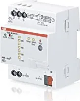
M: OA-GPT-5-NAN

© Copyright 2026 Manual.ly